Difference between revisions of "49-Way Joystick Conversion Board"
Jump to navigation
Jump to search
| Line 2: | Line 2: | ||
The Williams 49-Way Optical Joystick was advanced for the time. As the device relied on optical interrupter switches, there were no contacts to wear out or adjust. | The Williams 49-Way Optical Joystick was advanced for the time. As the device relied on optical interrupter switches, there were no contacts to wear out or adjust. | ||
<div class="toccolours mw-collapsible mw-collapsed" style="width:500px; overflow:auto;"> | <div class="toccolours mw-collapsible mw-collapsed" style="width:500px; overflow:auto;"> | ||
| − | <div style="font-weight:bold;line-height:1.6;"> | + | <div style="font-weight:bold;line-height:1.6;">Operation - Pinout</div> |
<div class="mw-collapsible-content"> | <div class="mw-collapsible-content"> | ||
| − | + | *3 Optical Interrupter Switches are used for each direction (Up/Down-Y and Left/Right -X) .Total of 6 switches | |
| − | + | **This provides a total of 7 possible positions in each X and Y axis. (3 Up/1 Center/3 Down - 3 Left/1 Center/3 Right) (7 * 7 = 49 Unique positions) | |
| − | + | *There are 8 unique outputs | |
| − | + | **Opto Swtich 1 (U/D) | |
| − | + | **Opto Switch 2 (U/D) | |
| − | + | **Opto Switch 3 (U/D) | |
| − | + | **Up/Down Direction | |
| − | + | **Opto Switch 4 (L/R) | |
| − | + | **Opto Switch 5 (L/R) | |
| − | + | **Opto Switch 6 (L/R) | |
| − | + | ** Left/Right Direction | |
| − | + | *12 Pin Molex Header Pin-Out | |
| − | + | *#+5 Volts | |
| − | + | *#Opto Switch 1 (U/D) | |
| − | + | *#Opto Switch 2 (U/D) | |
| − | + | *#Opto Switch 3 (U/D) | |
| − | + | *#Up/Down Direction (Up=Low / Down = High) | |
| − | + | *#Opto Switch 4 (L/R) | |
| − | + | *#Opto Switch 5 (L/R) | |
| − | + | *#Opto Switch 6 (L/R) | |
| − | + | *#Left/Right Direction (Right = Low / Left = High) | |
| − | + | *#Key - No Connection | |
| − | + | *#Ground | |
| − | + | *#Ground | |
| − | |||
</div></div> | </div></div> | ||
Revision as of 19:06, 24 March 2020
49-Way Joystick Information
The Williams 49-Way Optical Joystick was advanced for the time. As the device relied on optical interrupter switches, there were no contacts to wear out or adjust.
Operation - Pinout
- 3 Optical Interrupter Switches are used for each direction (Up/Down-Y and Left/Right -X) .Total of 6 switches
- This provides a total of 7 possible positions in each X and Y axis. (3 Up/1 Center/3 Down - 3 Left/1 Center/3 Right) (7 * 7 = 49 Unique positions)
- There are 8 unique outputs
- Opto Swtich 1 (U/D)
- Opto Switch 2 (U/D)
- Opto Switch 3 (U/D)
- Up/Down Direction
- Opto Switch 4 (L/R)
- Opto Switch 5 (L/R)
- Opto Switch 6 (L/R)
- Left/Right Direction
- 12 Pin Molex Header Pin-Out
- +5 Volts
- Opto Switch 1 (U/D)
- Opto Switch 2 (U/D)
- Opto Switch 3 (U/D)
- Up/Down Direction (Up=Low / Down = High)
- Opto Switch 4 (L/R)
- Opto Switch 5 (L/R)
- Opto Switch 6 (L/R)
- Left/Right Direction (Right = Low / Left = High)
- Key - No Connection
- Ground
- Ground
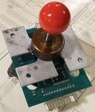
(Sinistar 49-Way)
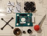
(Sinistar - Disassembled)
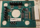
(49-Way PCB)
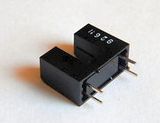
(Slotted Optical Switch
(Slotted Optical Switch Diagram)


Programmed Joystick Emulations
- The images and most of the information below is from Sean Riddle's site and the work he did building an EPROM based translator. You can visit his site HERE. (Thanks Sean!)
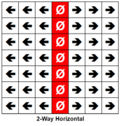
Horizontal)
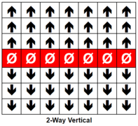
Vertical)

(4-Way)
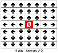
Corners U/D
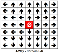
Corners L/R)
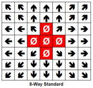
Standard)

With Dead Zone)

No Dead Zone)

(49-Way)


Amtel Microprocessor Source Code:
//Program Written By: Brad Raedel
//03162020 - Revision 1 - Just get it working

//Up
int Opto1 = 2;    //Input Pin 2
int Opto2 = 3;    //Input Pin 3
int Opto3 = 4;    //Input Pin 4
int Up = 10;      //Output to Game - Pin 10
int Dn = 11;      //Output to Game - Pin 11
//Down
int Opto4 = 5;    //Input Pin 5
int Opto5 = 6;    //Input Pin 6
int Opto6 = 7;    //Input Pin 7
int Left = 12;    //Output to Game - Pin 12
int Right = 13;   //Output to Game - Pin 13

//Option Switches - These will be used to select mode/options (0 to 15)
int Op1 = A0; //1
int Op2 = A1; //2
int Op3 = A2; //4
int Op4 = A3; //8
int OpVal = 0; //Default to zero

bool Opto1St;   //Opto States
bool Opto2St;
bool Opto3St;
bool Opto4St;
bool Opto5St;
bool Opto6St;
bool UpSt;      //Set HIGH when stick is UP
bool DnSt;      //Set HIGH when Stick is DOWN
bool LtSt;      //Set HIGH when stick is LEFT
bool RtSt;      //Set HIGH when Stick is RIGHT
bool LockedStUD;//Used to Latch the UP or DOWN position
bool LockedStLR;//Used to Latch the LEFT or RIGH postion
int UpVal = 3;    //Store the Up position (0-2)
int DnVal = 3;    //Store the Down postion (0-2)
int UpDnPos = 3;  //Absolute postion of Up/Down 0 = Top, 6 = Bottom, 3 is Center/Neutral
int LtVal = 3;    //Store the Left position (0-2)
int RtVal = 3;    //Store the Right position (0-2)
int LtRtPos = 3;  //Absolute postion of Left/Right 0 = Left, 6 = Right, 3 is Center/Neutral
int AbsPos = 24;

//Rows Then Columns - Stored Like this { {Row 0 - 0 to 48},{Row 2 - 0 to 48}...etc..
//Column Zero is the 8-Way With No Dead Zone
bool UpOut [1][49]  = { {1,1,1,1,1,1,1,1,1,1,1,1,1,1,0,0,1,1,1,0,0,0,0,0,0,0,0,0,0,0,0,0,0,0,0,0,0,0,0,0,0,0,0,0,0,0,0,0,0,} };
bool DnOut [1][49]  = { {0,0,0,0,0,0,0,0,0,0,0,0,0,0,0,0,0,0,0,0,0,0,0,0,0,0,0,0,0,0,1,1,1,0,0,1,1,1,1,1,1,1,1,1,1,1,1,1,1,} };
bool LtOut [1][49]  = { {1,1,0,0,0,0,0,1,1,0,0,0,0,0,1,1,1,0,0,0,0,1,1,1,0,0,0,0,1,1,1,0,0,0,0,1,1,0,0,0,0,0,1,1,0,0,0,0,0,} };
bool RtOut [1][49]  = { {0,0,0,0,0,1,1,0,0,0,0,0,1,1,0,0,0,0,1,1,1,0,0,0,0,1,1,1,0,0,0,0,1,1,1,0,0,0,0,0,1,1,0,0,0,0,0,1,1,} };
void setup() {
Serial.begin(57600);    //Disable when not debugging
pinMode(Opto1,INPUT);   //Set Direction of physical inputs/outputs
pinMode(Opto2,INPUT);
pinMode(Opto3,INPUT);
pinMode(Opto4,INPUT);
pinMode(Opto5,INPUT);
pinMode(Opto6,INPUT);
pinMode(Up,OUTPUT);
pinMode(Dn,OUTPUT);
pinMode(Left,OUTPUT);
pinMode(Right,OUTPUT);
pinMode(Op1,INPUT);
pinMode(Op2,INPUT);
pinMode(Op3,INPUT);
pinMode(Op4,INPUT);

//Let's get our DIP Switch settings (Will = 0 to 15)
if (digitalRead(Op1) == HIGH)
{
  OpVal = 1;
}
if (digitalRead(Op2) == HIGH)
{
  OpVal = OpVal + 2;
}
if (digitalRead(Op3) == HIGH)
{
  OpVal = OpVal +4;
}
if (digitalRead(Op4) == HIGH)
{
  OpVal = OpVal + 8;
}
//Serial.println(OpVal);

}

//Main Program that loops
void loop() {
// Up/Down Logic
Opto1St = digitalRead(Opto1); //Read Optical Switch 1
Opto2St = digitalRead(Opto2); //Read Optical Switch 2
Opto3St = digitalRead(Opto3); //Read Optical Switch 2
if (Opto1St == true && Opto2St == true && Opto3St == true)  //Determine if the joystick is in the center
{
  LockedStUD = false;   //Unlatch to allow Up or Down to assume control
  UpSt = false;         //Clear Up State
  DnSt = false;         //Clear Down State
  UpDnPos = 3;          //Set Vertical position to center
}
//Latch Direction (Determines if up or down
 if (Opto1St == false && LockedStUD == false)   //UP if True
      {
        UpSt = true;          //Set UP State to TRUE
        LockedStUD = true;    //We lock the State so DOWN can't Steal it!
      }
if (Opto3St == false && LockedStUD == false)    //DOWN if True
      {
        DnSt = true;        //Set DOWN State to TRUE
        LockedStUD = true;  //We lock the State so UP can't Steal it!
      }
//We will figure out what row we are in (0 to 6 - 3 is center)
if (UpSt == true) //Up doesn't need any change since adding the Optical Switches is 0 to 2
{
  UpVal = Opto1St + Opto2St + Opto3St;
  UpDnPos = UpVal;
}
if (DnSt == true)     //For Down, we determine how many Optical Switches are Low, add them up then use a look-up table to generate the position 4 to 6
{
  DnVal = Opto1St + Opto2St + Opto3St;
  switch (DnVal) {
  case 0:      //All Optos are LOW
      UpDnPos = 6;
  break;
  case 1:     //Two of the Optos are LOW
      UpDnPos = 5;
  break;
  case 2:    //One of the Optos are LOW (The others are still High)
      UpDnPos = 4;
  break;
  }
}

// Left/Right Logic
Opto4St = digitalRead(Opto4); //Read Optical Switch 4
Opto5St = digitalRead(Opto5); //Read Optical Switch 5
Opto6St = digitalRead(Opto6); //Read Optical Switch 6
if (Opto4St == true && Opto5St == true && Opto6St == true)  //Determine if the joystick is in the center
{
  LockedStLR = false;   //Unlatch to allow Left or Right to assume control
  LtSt = false;         //Clear Left State
  RtSt = false;         //Clear Right State
  LtRtPos = 3;          //Set Horizontal position to center
}
//Latch Direction (Determines if Left or Right
 if (Opto4St == false && LockedStLR == false)   //Right if True
      {
        RtSt = true;          //Set Right State to TRUE
        LockedStLR = true;    //We lock the State so Left can't Steal it!
      }
if (Opto6St == false && LockedStLR == false)    //Left if True
      {
        LtSt = true;        //Set Left State to TRUE
        LockedStLR = true;  //We lock the State so Right can't Steal it!
      }
//We will figure out what row we are in (0 to 6 - 3 is center)
if (LtSt == true) //Up doesn't need any change since adding the Optical Switches is 0 to 2
{
  LtVal = Opto4St + Opto5St + Opto6St;
  LtRtPos = LtVal;
}
if (RtSt == true)     //For Down, we determine how many Optical Switches are Low, add them up then use a look-up table to generate the position 4 to 6
{
  RtVal = Opto4St + Opto5St + Opto6St;
  switch (RtVal) {
  case 0:      //All Optos are LOW
      LtRtPos = 6;
  break;
  case 1:     //Two of the Optos are LOW
      LtRtPos = 5;
  break;
  case 2:    //One of the Optos are LOW (The others are still High)
      LtRtPos = 4;
  break;
  }
}
//Calculate the absolute position
AbsPos = (UpDnPos * 7) + LtRtPos;
   //Serial.println(AbsPos);
  digitalWrite(Up,!UpOut[0] [AbsPos]);
  digitalWrite(Dn,!DnOut[0][AbsPos]);
  digitalWrite(Left,!LtOut[0][AbsPos]);
  digitalWrite(Right,!RtOut[0][AbsPos]);
}
Interface Board (I/O, Widget)
Click here for more information..
Description: The interface board is used to provide input ports that allow the physical connection of user inputs from the Control Panel. This board uses a 6821 PIA (peripheral interface adapter) that digitizes all inputs and provides the switch state to the MPU board when requested.
- Jumpers
- W1
- Is used to identify to the system if the game is an Upright or Cocktail
- W1 Removed - Cocktail Game - Screen Flip and unique controls (+5v Pull-Up resistor to PIA)
- W1 Installed - Upright Game - 2 Players share same controls, no screen flip (Connects PIA input to Ground)
- Notes: Green Rom Version has no support for Cocktail Mode
- W2
- Is used to allow the program to enable or disable the Multiplexers (Muxers)
- W2 should always be connected there is no reason to remove jumper
- Connections
- Upright
- 3J2 Connector (Upper - Furthest from ribbon cable - Pin 1 is lowest - 10 Pin Molex PCB Headers - .156")
- 'Fire' Button - (ORG-BRN) - PIA Pin 2
- 'Thrust' Button - (ORG-RED) - PIA Pin 3
- 'Smart Bomb' Button - (ORG) - PIA Pin 4
- 'Hyperspace' Button - (ORG-YEL) - PIA Pin 5
- '2-Player Start' Button - (ORG-GRN) - PIA Pin 6
- '1-Player Start' Button - (ORG-BLU) - PIA Pin 7
- 'Reverse' Button - (ORG-VIO) - PIA Pin 8
- 'Down' Joystick - (ORG-GRY) - PIA Pin 9
- Key (Pin Removed)
- NC (No Connection)
- 3J3 Connector (Lower closest to ribbon cable - Pin 1 is lowest - 10 Pin Molex PCB Headers - .156")
- Up' Joystick - (ORG-WHT) - PIA Pin 10
- NC (No Connection)
- NC
- NC
- NC
- Key - Pin Removed
- NC
- NC
- NC
- Ground - (ORG-BLK) - Common to all switches and joystick
- Cocktail
- 3J2 Connector (Upper - Furthest from ribbon cable - Pin 1 is lowest - 10 Pin Molex PCB Headers - .156")
- 'Fire' Button (P1) - (ORG-BRN) - PIA Pin 2
- 'Thrust' Button (P1) - (ORG-RED) - PIA Pin 3
- 'Smart Bomb' Button (P1) - (ORG) - PIA Pin 4
- 'Hyperspace' Button (P1) - (ORG-YEL) - PIA Pin 5
- '2-Player Start' Button (P1) - (ORG-GRN) - PIA Pin 6
- '1-Player Start' Button (P1) - (ORG-BLU) - PIA Pin 7
- 'Reverse' Button (P1) - (ORG-VIO) - PIA Pin 8
- 'UP' Joystick (P1) - (ORG-GRY) - PIA Pin 9
- Key (Pin Removed)
- Ground - (RED-BLK) - Common to all P2 Controls)
- 3J3 Connector (Lower closest to ribbon cable - Pin 1 is lowest - 10 Pin Molex PCB Headers - .156")
- Down' Joystick (P1)- (ORG-WHT) - PIA Pin 10
- 'Up' Joystick (P2) - (RED-BRN)
- 'Thrust' Button (P2) - (RED)
- 'Smart Bomb' Button (P2) - (RED-ORG)
- 'Hyperspace' Button (P2) - (RED-YEL)
- Key - Pin Removed
- 'Reverse' Button (P2) - (RED-VIO)
- 'Fire' Button (P2) - (RED-GRY)
- 'Down' Joystick (P2) - (RED-WHT)
- Ground - (ORG-BLK) - (Common to all P1 Controls)
- Ribbon Cable - Pinout
- D4 - PIA Pin 29
- NMI(NOT) - PIA No Connection
- D7 - PIA Pin 26
- FIRQ(NOT) - PIA No Connection
- D6 - PIA Pin 27
- RW (Read/Write) - PIA Pin 21
- D5 - PIA Pin 28
- Reset(NOT) - PIA Pin 34
- D2 - PIA Pin 31
- +5vdc (Power for board) - PIA Pin 20
- D1 - PIA Pin 32
- D0 - PIA Pin 33
- D3 - PIA Pin 30
- E(Enable) - PIA Pin 25
- PIA(NOT) - PIA Pin 23 via IC4(14049 Hex Inverter Pin 11 to 12)
- Ground - PIA Pin 6
- A0 - PIA Pin 36
- A1 - PIA Pin 35
- A2 - PIA Pin 24
- A3 - PIA Pin 22 via IC4(14049 Hex Inverter - Pin 9 to 10)