Difference between revisions of "49-Way Joystick Conversion Board"
| (119 intermediate revisions by the same user not shown) | |||
| Line 1: | Line 1: | ||
| + | ==Custom PCB - Drop-In== | ||
| − | <gallery mode=" | + | This board is a drop-in replacement for the original 49-way(Sinistar/ArchRivals/Pigskin 621 AD). |
| − | Image: | + | |
| − | Image: | + | *;What does it do? |
| − | Image: | + | **Converts 49-Way Joysticks to 8-Way (or other types if desired) |
| − | Image: | + | **Uses all other hardware from the joystick besides the board |
| − | Image: | + | **ALL components on board are new including the Optical Switches |
| − | Image: | + | **Super easy installation |
| − | Image: | + | **Provides user ability to select Joystick type with DIP switches |
| − | Image: | + | **4 outputs are provided |
| − | Image: | + | ***Up |
| − | Image: | + | ***Down |
| − | Image: | + | ***Left |
| − | Image: | + | ***Right |
| − | + | **Uses Williams Standard 7-Pin connector and Pinout (Bubbles, Spat, Inferno, Joust-with rare 2-way optical sticks) | |
| − | + | **Default setting is for 8-Way that duplicates the dedicated Williams 8-Way Optical Joystick | |
| + | |||
| + | <youtube>https://www.youtube.com/watch?v=iR32MsdxWmM</youtube> | ||
| + | <youtube>https://www.youtube.com/watch?v=pvqfKHs7_PE</youtube> | ||
| + | <gallery mode="traditional" widths=260px heights=260px class="left"> | ||
| + | Image:PCB - REV A - GerberView Front.PNG |(PCB - Front) | ||
| + | Image:PCB - REV A - GerberView Rear.PNG | (PCB - Rear) | ||
| + | Image:8-Way Board - Populated.jpg | (Populated PCB) | ||
| + | Image:8-Way Board - Populated 2.jpg | (Populated PCB) | ||
| + | Image:8-Way Board - Mounted.jpg | (Mounted) | ||
| + | Image:49-Way Matrix Locations.PNG | (Mapped Locations) | ||
| + | Image:DIP Swich On PCB.jpg | (DIP Switch on PCB) | ||
| + | Image:49-Way-Joystick-Converter-Board-V2.png | (Schematic) | ||
| + | </gallery> | ||
| + | |||
| + | ==Connection Information== | ||
| + | [[File:8-Way Optical Joystick Pinout.png|300px]] | ||
| + | |||
| + | ==Programmed Joystick Emulation Modes - 10 Unique== | ||
| + | *Thanks to Sean Riddle for the work he did building an EPROM based translator. Lots of the information I used to develop this was from him. You can visit his site [https://seanriddle.com/49way.html HERE]. (Thanks Sean!) | ||
| + | |||
| + | '''Mode 0: 8-Way | Standard''' | ||
| + | <gallery mode="traditional" widths=250px heights=250px class="center"> | ||
| + | Image:Standard 8-Way.PNG|(8-Way - Standard * DEFAULT) | ||
| + | Image:00 - Zero SW.PNG | (DIP Switch Setting) | ||
| + | </gallery> | ||
| + | |||
| + | '''Mode 1: 8-Way | No Dead Zone''' | ||
| + | <gallery mode="traditional" widths=250px heights=250px class="center"> | ||
| + | Image:8-Way - No Dead Zone.PNG|(8-Way - No Dead Zone) | ||
| + | Image:01 - One SW.PNG | (DIP Switch Setting) | ||
| + | </gallery> | ||
| + | |||
| + | '''Mode 2: 8-Way | With Dead Zone''' | ||
| + | <gallery mode="traditional" widths=250px heights=250px class="center"> | ||
| + | Image:8-Way - With Dead Zone.PNG|(8-Way - With Dead Zone) | ||
| + | Image:02 - Two SW.PNG | (DIP Switch Setting) | ||
| + | </gallery> | ||
| + | |||
| + | '''Mode 3: 4-Way | Standard''' | ||
| + | <gallery mode="traditional" widths=250px heights=250px class="center"> | ||
| + | Image:4-Way Standard.PNG|(4-Way) | ||
| + | Image:03 - Three SW.PNG | (DIP Switch Setting) | ||
| + | </gallery> | ||
| + | |||
| + | '''Mode 4: 4-Way | With Dead Zone''' | ||
| + | <gallery mode="traditional" widths=250px heights=250px class="center"> | ||
| + | Image:4-Way - Dead Zone.PNG|(4-Way - Dead Zone) | ||
| + | Image:04 - Four SW.PNG | (DIP Switch Setting) | ||
| + | </gallery> | ||
| + | |||
| + | '''Mode 5: 4-Way | Corners Left/Right''' | ||
| + | <gallery mode="traditional" widths=250px heights=250px class="center"> | ||
| + | Image:4-Way - Corners L-R.PNG|(4-Way - Corners L/R) | ||
| + | Image:05 - Five SW .PNG | (DIP Switch Setting) | ||
| + | </gallery> | ||
| + | |||
| + | '''Mode 6: 4-Way | Corners Up/Down''' | ||
| + | <gallery mode="traditional" widths=250px heights=250px class="center"> | ||
| + | Image:4-Way - Corners U-D.PNG | 4-Way - Corners U/D | ||
| + | Image:06 - Six SW.PNG | (DIP Switch Setting) | ||
| + | </gallery> | ||
| + | |||
| + | '''Mode 7: 2-Way | Horizontal''' | ||
| + | <gallery mode="traditional" widths=250px heights=250px class="center"> | ||
| + | Image:2-Way - Horizontal.PNG|(2-Way - Horizontal) | ||
| + | Image:07 - Seven SW.PNG | (DIP Switch Setting) | ||
| + | </gallery> | ||
| + | |||
| + | '''Mode 8: 2-Way | Vertical''' | ||
| + | <gallery mode="traditional" widths=250px heights=250px class="center"> | ||
| + | Image:2-Way - Vertical.PNG|(2-Way - Vertical) | ||
| + | Image:08 - Eight SW.PNG | (DIP Switch Setting) | ||
| + | </gallery> | ||
| + | |||
| + | '''Mode 9: Diagonal''' | ||
| + | <gallery mode="traditional" widths=250px heights=250px class="center"> | ||
| + | Image:Diagonal.PNG|(Diagonal) | ||
| + | Image:09 - Nine SW.PNG | (DIP Switch Setting) | ||
</gallery> | </gallery> | ||
| + | |||
| + | ==49-Way Joystick Information== | ||
| + | The Williams 49-Way Optical Joystick was advanced for the time. As the device relied on optical interrupter switches, there were no contacts to wear out or adjust. | ||
| + | |||
| + | ==Original 49-Way== | ||
| + | <div class="toccolours mw-collapsible mw-collapsed" style="width:500px; overflow:auto;"> | ||
| + | <div style="font-weight:bold;line-height:1.6;">Operation - Pinout</div> | ||
| + | <div class="mw-collapsible-content"> | ||
| + | *3 Optical Interrupter Switches are used for each direction (Up/Down-Y and Left/Right -X) .Total of 6 switches | ||
| + | **This provides a total of 7 possible positions in each X and Y axis. (3 Up/1 Center/3 Down - 3 Left/1 Center/3 Right) (7 * 7 = 49 Unique positions) | ||
| + | *There are 8 unique outputs | ||
| + | **Opto Swtich 1 (U/D - A) | ||
| + | **Opto Switch 2 (U/D - B) | ||
| + | **Opto Switch 3 (U/D - C) | ||
| + | **Up/Down Direction | ||
| + | **Opto Switch 4 (L/R - A) | ||
| + | **Opto Switch 5 (L/R - B) | ||
| + | **Opto Switch 6 (L/R - C) | ||
| + | ** Left/Right Direction | ||
| + | *12 Pin Molex Header Pin-Out | ||
| + | *#+5 Volts | ||
| + | *#Opto Switch 1 (U/D - A) | ||
| + | *#Opto Switch 2 (U/D - B) | ||
| + | *#Opto Switch 3 (U/D - C) | ||
| + | *#Up/Down Direction (Up=Low / Down = High) | ||
| + | *#Opto Switch 4 (L/R - A) | ||
| + | *#Opto Switch 5 (L/R - B) | ||
| + | *#Opto Switch 6 (L/R - C) | ||
| + | *#Left/Right Direction (Right = Low / Left = High) | ||
| + | *#Key - No Connection | ||
| + | *#Ground | ||
| + | *#Ground | ||
| + | </div></div> | ||
| + | <gallery mode="traditional" widths=160px heights=160px class="left"> | ||
| + | Image:Sinistar - 49-Way Joystick.jpg|(Sinistar 49-Way) | ||
| + | Image:Sinistar 49-Way - Disassembled.jpg | (Sinistar - Disassembled) | ||
| + | Image:49-Way - PCB.jpg|(49-Way PCB) | ||
| + | Image: Slotted Optical Switch.jpg|(Slotted Optical Switch | ||
| + | Image:Photo Interrupter - Slotted Optical Switch.gif|(Slotted Optical Switch Diagram) | ||
| + | </gallery> | ||
| + | |||
| + | <!-- [[File:Williams Flyer.jpg|right|300px]] --> | ||
| + | |||
| + | ==Atmel Microprocessor Source Code:== | ||
| + | <nowiki> | ||
| + | |||
| + | //Program Written By: Brad Raedel | ||
| + | //03242020 - Revision A | ||
| + | //** All 8 Profiles active | ||
| + | //** Outputs now change to inputs when not active - This allows the pull-up resistors to control the high logic | ||
| + | //03162020 - Revision 1 - Just get it working | ||
| + | |||
| + | //Up | ||
| + | int Opto1 = 2; //Input Pin 2 | ||
| + | int Opto2 = 3; //Input Pin 3 | ||
| + | int Opto3 = 4; //Input Pin 4 | ||
| + | int Up = 9; //Output to Game - Pin 10 | ||
| + | int Dn = 10; //Output to Game - Pin 11 | ||
| + | //Down | ||
| + | int Opto4 = 5; //Input Pin 5 | ||
| + | int Opto5 = 6; //Input Pin 6 | ||
| + | int Opto6 = 7; //Input Pin 7 | ||
| + | int Left = 11; //Output to Game - Pin 12 | ||
| + | int Right = 12; //Output to Game - Pin 13 | ||
| + | |||
| + | //Option Switches - These will be used to select mode/options (0 to 15) | ||
| + | int Op1 = A0; //1 | ||
| + | int Op2 = A1; //2 | ||
| + | int Op3 = A2; //4 | ||
| + | int Op4 = A3; //8 | ||
| + | int OpVal = 0; //Default to zero | ||
| + | |||
| + | bool Opto1St; //Opto States | ||
| + | bool Opto2St; | ||
| + | bool Opto3St; | ||
| + | bool Opto4St; | ||
| + | bool Opto5St; | ||
| + | bool Opto6St; | ||
| + | bool UpSt; //Set HIGH when stick is UP | ||
| + | bool DnSt; //Set HIGH when Stick is DOWN | ||
| + | bool LtSt; //Set HIGH when stick is LEFT | ||
| + | bool RtSt; //Set HIGH when Stick is RIGHT | ||
| + | bool LockedStUD;//Used to Latch the UP or DOWN position | ||
| + | bool LockedStLR;//Used to Latch the LEFT or RIGH postion | ||
| + | int UpVal = 3; //Store the Up position (0-2) | ||
| + | int DnVal = 3; //Store the Down postion (0-2) | ||
| + | int UpDnPos = 3; //Absolute postion of Up/Down 0 = Top, 6 = Bottom, 3 is Center/Neutral | ||
| + | int LtVal = 3; //Store the Left position (0-2) | ||
| + | int RtVal = 3; //Store the Right position (0-2) | ||
| + | int LtRtPos = 3; //Absolute postion of Left/Right 0 = Left, 6 = Right, 3 is Center/Neutral | ||
| + | int AbsPos = 24; | ||
| + | int i = 0; | ||
| + | |||
| + | //Rows Then Columns - Stored Like this { {Row 0 - 0 to 48},{Row 2 - 0 to 48}...etc.. | ||
| + | // 8-Way Standard | ||
| + | const bool Up8WayStd[49] = {1,1,1,1,1,1,1,1,1,1,1,1,1,1,0,0,1,0,1,0,0,0,0,0,0,0,0,0,0,0,0,0,0,0,0,0,0,0,0,0,0,0,0,0,0,0,0,0,0} ; | ||
| + | const bool Dn8WayStd[49] = {0,0,0,0,0,0,0,0,0,0,0,0,0,0,0,0,0,0,0,0,0,0,0,0,0,0,0,0,0,0,1,0,1,0,0,1,1,1,1,1,1,1,1,1,1,1,1,1,1} ; | ||
| + | const bool Lt8WayStd[49] = {1,1,0,0,0,0,0,1,1,0,0,0,0,0,1,1,1,0,0,0,0,1,1,0,0,0,0,0,1,1,1,0,0,0,0,1,1,0,0,0,0,0,1,1,0,0,0,0,0} ; | ||
| + | const bool Rt8WayStd[49] = {0,0,0,0,0,1,1,0,0,0,0,0,1,1,0,0,0,0,1,1,1,0,0,0,0,0,1,1,0,0,0,0,1,1,1,0,0,0,0,0,1,1,0,0,0,0,0,1,1} ; | ||
| + | // 8-Way with NO Dead Zone | ||
| + | const bool Up8WayNoDZ[49] = {1,1,1,1,1,1,1,1,1,1,1,1,1,1,0,0,1,1,1,0,0,0,0,0,0,0,0,0,0,0,0,0,0,0,0,0,0,0,0,0,0,0,0,0,0,0,0,0,0} ; | ||
| + | const bool Dn8WayNoDZ[49] = {0,0,0,0,0,0,0,0,0,0,0,0,0,0,0,0,0,0,0,0,0,0,0,0,0,0,0,0,0,0,1,1,1,0,0,1,1,1,1,1,1,1,1,1,1,1,1,1,1} ; | ||
| + | const bool Lt8WayNoDZ[49] = {1,1,0,0,0,0,0,1,1,0,0,0,0,0,1,1,1,0,0,0,0,1,1,1,0,0,0,0,1,1,1,0,0,0,0,1,1,0,0,0,0,0,1,1,0,0,0,0,0} ; | ||
| + | const bool Rt8WayNoDZ[49] = {0,0,0,0,0,1,1,0,0,0,0,0,1,1,0,0,0,0,1,1,1,0,0,0,0,1,1,1,0,0,0,0,1,1,1,0,0,0,0,0,1,1,0,0,0,0,0,1,1} ; | ||
| + | // 8-Way with Dead Zone | ||
| + | const bool Up8WayDZ[49] = {1,1,1,1,1,1,1,1,1,1,1,1,1,1,0,0,0,0,0,0,0,0,0,0,0,0,0,0,0,0,0,0,0,0,0,0,0,0,0,0,0,0,0,0,0,0,0,0,0} ; | ||
| + | const bool Dn8WayDZ[49] = {0,0,0,0,0,0,0,0,0,0,0,0,0,0,0,0,0,0,0,0,0,0,0,0,0,0,0,0,0,0,0,0,0,0,0,1,1,1,1,1,1,1,1,1,1,1,1,1,1} ; | ||
| + | const bool Lt8WayDZ[49] = {1,1,0,0,0,0,0,1,1,0,0,0,0,0,1,1,0,0,0,0,0,1,1,0,0,0,0,0,1,1,0,0,0,0,0,1,1,0,0,0,0,0,1,1,0,0,0,0,0} ; | ||
| + | const bool Rt8WayDZ[49] = {0,0,0,0,0,1,1,0,0,0,0,0,1,1,0,0,0,0,0,1,1,0,0,0,0,0,1,1,0,0,0,0,0,1,1,0,0,0,0,0,1,1,0,0,0,0,0,1,1} ; | ||
| + | //4-Way Standard | ||
| + | const bool Up4WayStd[49] = {0,1,1,1,1,1,0,0,0,1,1,1,0,0,0,0,0,1,0,0,0,0,0,0,0,0,0,0,0,0,0,0,0,0,0,0,0,0,0,0,0,0,0,0,0,0,0,0,0} ; | ||
| + | const bool Dn4WayStd[49] = {0,0,0,0,0,0,0,0,0,0,0,0,0,0,0,0,0,0,0,0,0,0,0,0,0,0,0,0,0,0,0,1,0,0,0,0,0,1,1,1,0,0,0,0,1,1,1,1,0} ; | ||
| + | const bool Lt4WayStd[49] = {0,0,0,0,0,0,0,1,0,0,0,0,0,0,1,1,0,0,0,0,0,1,1,1,0,0,0,0,1,1,0,0,0,0,0,1,0,0,0,0,0,0,0,0,0,0,0,0,0} ; | ||
| + | const bool Rt4WayStd[49] = {0,0,0,0,0,0,0,0,0,0,0,0,0,1,0,0,0,0,0,1,1,0,0,0,0,1,1,1,0,0,0,0,0,1,1,0,0,0,0,0,0,1,0,0,0,0,0,0,0} ; | ||
| + | //4-Way Corners L/R | ||
| + | const bool Up4WayLR[49] = {0,1,1,1,1,1,0,0,1,1,1,1,1,0,0,0,0,1,0,0,0,0,0,0,0,0,0,0,0,0,0,0,0,0,0,0,0,0,0,0,0,0,0,0,0,0,0,0,0} ; | ||
| + | const bool Dn4WayLR[49] = {0,0,0,0,0,0,0,0,0,0,0,0,0,0,0,0,0,0,0,0,0,0,0,0,0,0,0,0,0,0,0,1,0,0,0,0,1,1,1,1,1,0,0,1,1,1,1,1,0} ; | ||
| + | const bool Lt4WayLR[49] = {1,0,0,0,0,0,0,1,0,0,0,0,0,0,1,1,1,0,0,0,0,1,1,1,0,0,0,0,1,1,1,0,0,0,0,1,0,0,0,0,0,0,1,0,0,0,0,0,0} ; | ||
| + | const bool Rt4WayLR[49] = {0,0,0,0,0,0,1,0,0,0,0,0,0,1,0,0,0,0,1,1,1,0,0,0,0,1,1,1,0,0,0,0,1,1,1,0,0,0,0,0,0,1,0,0,0,0,0,0,1} ; | ||
| + | //4-Way Corners U/D | ||
| + | const bool Up4WayUD[49] = {1,1,1,1,1,1,1,0,1,1,1,1,1,0,0,0,1,1,1,0,0,0,0,0,0,0,0,0,0,0,0,0,0,0,0,0,0,0,0,0,0,0,0,0,0,0,0,0,0} ; | ||
| + | const bool Dn4WayUD[49] = {0,0,0,0,0,0,0,0,0,0,0,0,0,0,0,0,0,0,0,0,0,0,0,0,0,0,0,0,0,0,1,1,1,0,0,0,1,1,1,1,1,0,1,1,1,1,1,1,1} ; | ||
| + | const bool Lt4WayUD[49] = {0,0,0,0,0,0,0,1,0,0,0,0,0,0,1,1,0,0,0,0,0,1,1,1,0,0,0,0,1,1,0,0,0,0,0,1,0,0,0,0,0,0,0,0,0,0,0,0,0} ; | ||
| + | const bool Rt4WayUD[49] = {0,0,0,0,0,0,0,0,0,0,0,0,0,1,0,0,0,0,0,1,1,0,0,0,0,1,1,1,0,0,0,0,0,1,1,0,0,0,0,0,0,1,0,0,0,0,0,0,0} ; | ||
| + | // 2-Way Horizontal | ||
| + | const bool Up2WayH[49] = {0,0,0,0,0,0,0,0,0,0,0,0,0,0,0,0,0,0,0,0,0,0,0,0,0,0,0,0,0,0,0,0,0,0,0,0,0,0,0,0,0,0,0,0,0,0,0,0,0} ; | ||
| + | const bool Dn2WayH[49] = {0,0,0,0,0,0,0,0,0,0,0,0,0,0,0,0,0,0,0,0,0,0,0,0,0,0,0,0,0,0,0,0,0,0,0,0,0,0,0,0,0,0,0,0,0,0,0,0,0} ; | ||
| + | const bool Lt2WayH[49] = {1,1,1,0,0,0,0,1,1,1,0,0,0,0,1,1,1,0,0,0,0,1,1,1,0,0,0,0,1,1,1,0,0,0,0,1,1,1,0,0,0,0,1,1,1,0,0,0,0} ; | ||
| + | const bool Rt2WayH[49] = {0,0,0,0,1,1,1,0,0,0,0,1,1,1,0,0,0,0,1,1,1,0,0,0,0,1,1,1,0,0,0,0,1,1,1,0,0,0,0,1,1,1,0,0,0,0,1,1,1} ; | ||
| + | // 2-Way Vertical | ||
| + | const bool Up2WayV[49] = {1,1,1,1,1,1,1,1,1,1,1,1,1,1,1,1,1,1,1,1,1,0,0,0,0,0,0,0,0,0,0,0,0,0,0,0,0,0,0,0,0,0,0,0,0,0,0,0,0} ; | ||
| + | const bool Dn2WayV[49] = {0,0,0,0,0,0,0,0,0,0,0,0,0,0,0,0,0,0,0,0,0,0,0,0,0,0,0,0,1,1,1,1,1,1,1,1,1,1,1,1,1,1,1,1,1,1,1,1,1} ; | ||
| + | const bool Lt2WayV[49] = {0,0,0,0,0,0,0,0,0,0,0,0,0,0,0,0,0,0,0,0,0,0,0,0,0,0,0,0,0,0,0,0,0,0,0,0,0,0,0,0,0,0,0,0,0,0,0,0,0} ; | ||
| + | const bool Rt2WayV[49] = {0,0,0,0,0,0,0,0,0,0,0,0,0,0,0,0,0,0,0,0,0,0,0,0,0,0,0,0,0,0,0,0,0,0,0,0,0,0,0,0,0,0,0,0,0,0,0,0,0} ; | ||
| + | |||
| + | bool UpOut[49] = {}; | ||
| + | bool DnOut[49] = {}; | ||
| + | bool LtOut[49] = {}; | ||
| + | bool RtOut[49] = {}; | ||
| + | void setup() { | ||
| + | //Serial.begin(57600); //Disable when not debugging | ||
| + | pinMode(Opto1,INPUT); //Set Direction of physical inputs/outputs | ||
| + | pinMode(Opto2,INPUT); | ||
| + | pinMode(Opto3,INPUT); | ||
| + | pinMode(Opto4,INPUT); | ||
| + | pinMode(Opto5,INPUT); | ||
| + | pinMode(Opto6,INPUT); | ||
| + | pinMode(Up,INPUT); | ||
| + | pinMode(Dn,INPUT); | ||
| + | pinMode(Left,INPUT); | ||
| + | pinMode(Right,INPUT); | ||
| + | pinMode(Op1,INPUT); | ||
| + | pinMode(Op2,INPUT); | ||
| + | pinMode(Op3,INPUT); | ||
| + | pinMode(Op4,INPUT); | ||
| + | |||
| + | //Let's get our DIP Switch settings (Will = 0 to 15) | ||
| + | if (digitalRead(Op1) == HIGH) | ||
| + | { | ||
| + | OpVal = 1; | ||
| + | } | ||
| + | if (digitalRead(Op2) == HIGH) | ||
| + | { | ||
| + | OpVal = OpVal + 2; | ||
| + | } | ||
| + | if (digitalRead(Op3) == HIGH) | ||
| + | { | ||
| + | OpVal = OpVal + 4; | ||
| + | } | ||
| + | if (digitalRead(Op4) == HIGH) | ||
| + | { | ||
| + | OpVal = OpVal + 8; | ||
| + | } | ||
| + | //Serial.println(OpVal); | ||
| + | switch (OpVal) { | ||
| + | case 0: //DIP Switch 0 - 8-Way - No Dead zone - This routine copies the array - Only on setup, not during loop/runtime | ||
| + | // 8WayStd | ||
| + | i = 0; | ||
| + | while( i < 49 ){ | ||
| + | UpOut[ i ] = Up8WayStd[ i ]; | ||
| + | DnOut[ i ] = Dn8WayStd[ i ]; | ||
| + | LtOut[ i ] = Lt8WayStd[ i ]; | ||
| + | RtOut[ i ] = Rt8WayStd[ i ]; | ||
| + | ++i;} | ||
| + | break; | ||
| + | case 1: //DIP Switch 1 - | ||
| + | // 8WayNoDZ | ||
| + | i = 0; | ||
| + | while( i < 49 ){ | ||
| + | UpOut[ i ] = Up8WayNoDZ[ i ]; | ||
| + | DnOut[ i ] = Dn8WayNoDZ[ i ]; | ||
| + | LtOut[ i ] = Lt8WayNoDZ[ i ]; | ||
| + | RtOut[ i ] = Rt8WayNoDZ[ i ]; | ||
| + | ++i;} | ||
| + | break; | ||
| + | case 2: //DIP Switch 2 - | ||
| + | // 8WayDZ | ||
| + | i = 0; | ||
| + | while( i < 49 ){ | ||
| + | UpOut[ i ] = Up8WayDZ[ i ]; | ||
| + | DnOut[ i ] = Dn8WayDZ[ i ]; | ||
| + | LtOut[ i ] = Lt8WayDZ[ i ]; | ||
| + | RtOut[ i ] = Rt8WayDZ[ i ]; | ||
| + | ++i;} | ||
| + | break; | ||
| + | case 3: //DIP Switch 3 - | ||
| + | // 4WayStd | ||
| + | i = 0; | ||
| + | while( i < 49 ){ | ||
| + | UpOut[ i ] = Up4WayStd[ i ]; | ||
| + | DnOut[ i ] = Dn4WayStd[ i ]; | ||
| + | LtOut[ i ] = Lt4WayStd[ i ]; | ||
| + | RtOut[ i ] = Rt4WayStd[ i ]; | ||
| + | ++i;} | ||
| + | break; | ||
| + | case 4: //DIP Switch 4 - | ||
| + | // 4WayLR | ||
| + | i = 0; | ||
| + | while( i < 49 ){ | ||
| + | UpOut[ i ] = Up4WayLR[ i ]; | ||
| + | DnOut[ i ] = Dn4WayLR[ i ]; | ||
| + | LtOut[ i ] = Lt4WayLR[ i ]; | ||
| + | RtOut[ i ] = Rt4WayLR[ i ]; | ||
| + | ++i;} | ||
| + | break; | ||
| + | case 5: //DIP Switch 5 - | ||
| + | // 4WayUD | ||
| + | i = 0; | ||
| + | while( i < 49 ){ | ||
| + | UpOut[ i ] = Up4WayUD[ i ]; | ||
| + | DnOut[ i ] = Dn4WayUD[ i ]; | ||
| + | LtOut[ i ] = Lt4WayUD[ i ]; | ||
| + | RtOut[ i ] = Rt4WayUD[ i ]; | ||
| + | ++i;} | ||
| + | break; | ||
| + | case 6: //DIP Switch 6 - | ||
| + | // 2WayH | ||
| + | i = 0; | ||
| + | while( i < 49 ){ | ||
| + | UpOut[ i ] = Up2WayH[ i ]; | ||
| + | DnOut[ i ] = Dn2WayH[ i ]; | ||
| + | LtOut[ i ] = Lt2WayH[ i ]; | ||
| + | RtOut[ i ] = Rt2WayH[ i ]; | ||
| + | ++i;} | ||
| + | break; | ||
| + | case 7: //DIP Switch 7 - | ||
| + | // 2WayV | ||
| + | i = 0; | ||
| + | while( i < 49 ){ | ||
| + | UpOut[ i ] = Up2WayV[ i ]; | ||
| + | DnOut[ i ] = Dn2WayV[ i ]; | ||
| + | LtOut[ i ] = Lt2WayV[ i ]; | ||
| + | RtOut[ i ] = Rt2WayV[ i ]; | ||
| + | ++i;} | ||
| + | break; | ||
| + | |||
| + | } | ||
| + | } | ||
| + | |||
| + | //Main Program that loops | ||
| + | void loop() { | ||
| + | // Up/Down Logic | ||
| + | Opto1St = digitalRead(Opto1); //Read Optical Switch 1 | ||
| + | Opto2St = digitalRead(Opto2); //Read Optical Switch 2 | ||
| + | Opto3St = digitalRead(Opto3); //Read Optical Switch 2 | ||
| + | if (Opto1St == true && Opto2St == true && Opto3St == true) //Determine if the joystick is in the center | ||
| + | { | ||
| + | LockedStUD = false; //Unlatch to allow Up or Down to assume control | ||
| + | UpSt = false; //Clear Up State | ||
| + | DnSt = false; //Clear Down State | ||
| + | UpDnPos = 3; //Set Vertical position to center | ||
| + | } | ||
| + | //Latch Direction (Determines if up or down | ||
| + | if (Opto1St == false && LockedStUD == false) //UP if True | ||
| + | { | ||
| + | UpSt = true; //Set UP State to TRUE | ||
| + | LockedStUD = true; //We lock the State so DOWN can't Steal it! | ||
| + | } | ||
| + | if (Opto3St == false && LockedStUD == false) //DOWN if True | ||
| + | { | ||
| + | DnSt = true; //Set DOWN State to TRUE | ||
| + | LockedStUD = true; //We lock the State so UP can't Steal it! | ||
| + | } | ||
| + | //We will figure out what row we are in (0 to 6 - 3 is center) | ||
| + | if (UpSt == true) //Up doesn't need any change since adding the Optical Switches is 0 to 2 | ||
| + | { | ||
| + | UpVal = Opto1St + Opto2St + Opto3St; | ||
| + | UpDnPos = UpVal; | ||
| + | } | ||
| + | if (DnSt == true) //For Down, we determine how many Optical Switches are Low, add them up then use a look-up table to generate the position 4 to 6 | ||
| + | { | ||
| + | DnVal = Opto1St + Opto2St + Opto3St; | ||
| + | switch (DnVal) { | ||
| + | case 0: //All Optos are LOW | ||
| + | UpDnPos = 6; | ||
| + | break; | ||
| + | case 1: //Two of the Optos are LOW | ||
| + | UpDnPos = 5; | ||
| + | break; | ||
| + | case 2: //One of the Optos are LOW (The others are still High) | ||
| + | UpDnPos = 4; | ||
| + | break; | ||
| + | } | ||
| + | } | ||
| + | |||
| + | // Left/Right Logic | ||
| + | Opto4St = digitalRead(Opto4); //Read Optical Switch 4 | ||
| + | Opto5St = digitalRead(Opto5); //Read Optical Switch 5 | ||
| + | Opto6St = digitalRead(Opto6); //Read Optical Switch 6 | ||
| + | if (Opto4St == true && Opto5St == true && Opto6St == true) //Determine if the joystick is in the center | ||
| + | { | ||
| + | LockedStLR = false; //Unlatch to allow Left or Right to assume control | ||
| + | LtSt = false; //Clear Left State | ||
| + | RtSt = false; //Clear Right State | ||
| + | LtRtPos = 3; //Set Horizontal position to center | ||
| + | } | ||
| + | //Latch Direction (Determines if Left or Right | ||
| + | if (Opto4St == false && LockedStLR == false) //Right if True | ||
| + | { | ||
| + | RtSt = true; //Set Right State to TRUE | ||
| + | LockedStLR = true; //We lock the State so Left can't Steal it! | ||
| + | } | ||
| + | if (Opto6St == false && LockedStLR == false) //Left if True | ||
| + | { | ||
| + | LtSt = true; //Set Left State to TRUE | ||
| + | LockedStLR = true; //We lock the State so Right can't Steal it! | ||
| + | } | ||
| + | //We will figure out what row we are in (0 to 6 - 3 is center) | ||
| + | if (LtSt == true) //Up doesn't need any change since adding the Optical Switches is 0 to 2 | ||
| + | { | ||
| + | LtVal = Opto4St + Opto5St + Opto6St; | ||
| + | LtRtPos = LtVal; | ||
| + | } | ||
| + | if (RtSt == true) //For Down, we determine how many Optical Switches are Low, add them up then use a look-up table to generate the position 4 to 6 | ||
| + | { | ||
| + | RtVal = Opto4St + Opto5St + Opto6St; | ||
| + | switch (RtVal) { | ||
| + | case 0: //All Optos are LOW | ||
| + | LtRtPos = 6; | ||
| + | break; | ||
| + | case 1: //Two of the Optos are LOW | ||
| + | LtRtPos = 5; | ||
| + | break; | ||
| + | case 2: //One of the Optos are LOW (The others are still High) | ||
| + | LtRtPos = 4; | ||
| + | break; | ||
| + | } | ||
| + | } | ||
| + | //Calculate the absolute position | ||
| + | AbsPos = (UpDnPos * 7) + LtRtPos; | ||
| + | //Serial.println(AbsPos); | ||
| + | //Output | ||
| + | //UP | ||
| + | if (UpOut[AbsPos] == true){ | ||
| + | pinMode(Up,OUTPUT); | ||
| + | digitalWrite(Up,LOW); | ||
| + | } | ||
| + | else { | ||
| + | pinMode(Up,INPUT); | ||
| + | } | ||
| + | //Down | ||
| + | if (DnOut[AbsPos] == true){ | ||
| + | pinMode(Dn,OUTPUT); | ||
| + | digitalWrite(Dn,LOW); | ||
| + | } | ||
| + | else { | ||
| + | pinMode(Dn,INPUT); | ||
| + | } | ||
| + | //Left | ||
| + | if (LtOut[AbsPos] == true){ | ||
| + | pinMode(Left,OUTPUT); | ||
| + | digitalWrite(Left,LOW); | ||
| + | } | ||
| + | else { | ||
| + | pinMode(Left,INPUT); | ||
| + | } | ||
| + | //Right | ||
| + | if (RtOut[AbsPos] == true){ | ||
| + | pinMode(Right,OUTPUT); | ||
| + | digitalWrite(Right,LOW); | ||
| + | } | ||
| + | else { | ||
| + | pinMode(Right,INPUT); | ||
| + | } | ||
| + | } | ||
| + | </nowiki> | ||
Latest revision as of 11:48, 17 July 2020
Contents
Custom PCB - Drop-In
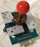
This board is a drop-in replacement for the original 49-way(Sinistar/ArchRivals/Pigskin 621 AD).
- What does it do?
- Converts 49-Way Joysticks to 8-Way (or other types if desired)
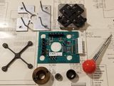
- Uses all other hardware from the joystick besides the board
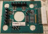
- ALL components on board are new including the Optical Switches
- Super easy installation
- Provides user ability to select Joystick type with DIP switches
- 4 outputs are provided
- Up
- Down
- Left
- Right
- Uses Williams Standard 7-Pin connector and Pinout (Bubbles, Spat, Inferno, Joust-with rare 2-way optical sticks)
- Default setting is for 8-Way that duplicates the dedicated Williams 8-Way Optical Joystick
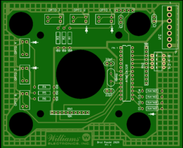
(PCB - Front)
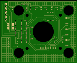
(PCB - Rear)
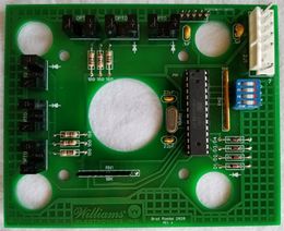
(Populated PCB)
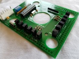
(Populated PCB)
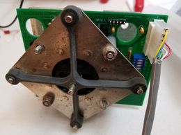
(Mounted)
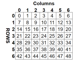
(Mapped Locations)
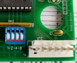
(DIP Switch on PCB)
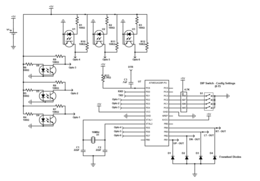
(Schematic)


Connection Information

Programmed Joystick Emulation Modes - 10 Unique
- Thanks to Sean Riddle for the work he did building an EPROM based translator. Lots of the information I used to develop this was from him. You can visit his site HERE. (Thanks Sean!)
Mode 0: 8-Way | Standard
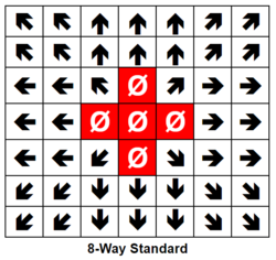
(8-Way - Standard * DEFAULT)
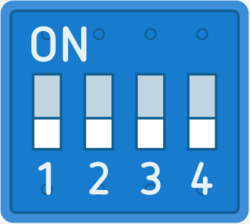
(DIP Switch Setting)


Mode 1: 8-Way | No Dead Zone
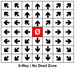
(8-Way - No Dead Zone)
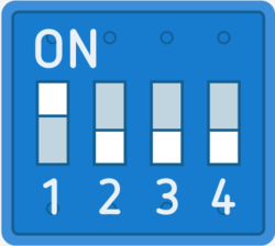
(DIP Switch Setting)


Mode 2: 8-Way | With Dead Zone
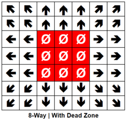
(8-Way - With Dead Zone)
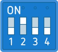
(DIP Switch Setting)


Mode 3: 4-Way | Standard
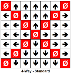
(4-Way)
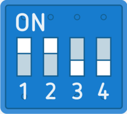
(DIP Switch Setting)


Mode 4: 4-Way | With Dead Zone
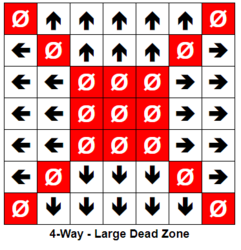
(4-Way - Dead Zone)
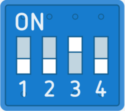
(DIP Switch Setting)


Mode 5: 4-Way | Corners Left/Right
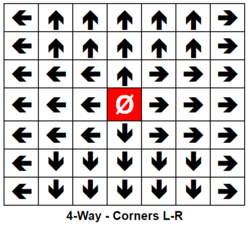
(4-Way - Corners L/R)
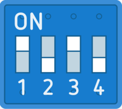
(DIP Switch Setting)


Mode 6: 4-Way | Corners Up/Down
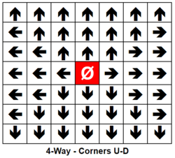
4-Way - Corners U/D
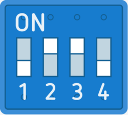
(DIP Switch Setting)


Mode 7: 2-Way | Horizontal
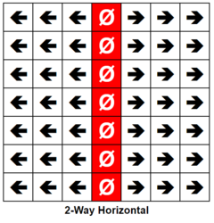
(2-Way - Horizontal)
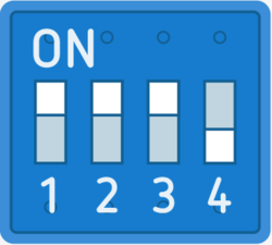
(DIP Switch Setting)


Mode 8: 2-Way | Vertical
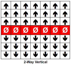
(2-Way - Vertical)
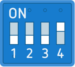
(DIP Switch Setting)


Mode 9: Diagonal
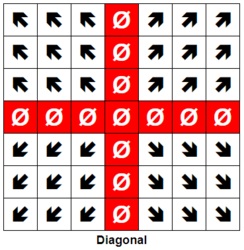
(Diagonal)
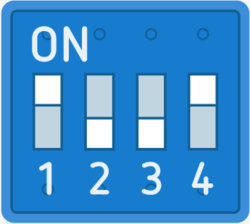
(DIP Switch Setting)


49-Way Joystick Information
The Williams 49-Way Optical Joystick was advanced for the time. As the device relied on optical interrupter switches, there were no contacts to wear out or adjust.
Original 49-Way
- 3 Optical Interrupter Switches are used for each direction (Up/Down-Y and Left/Right -X) .Total of 6 switches
- This provides a total of 7 possible positions in each X and Y axis. (3 Up/1 Center/3 Down - 3 Left/1 Center/3 Right) (7 * 7 = 49 Unique positions)
- There are 8 unique outputs
- Opto Swtich 1 (U/D - A)
- Opto Switch 2 (U/D - B)
- Opto Switch 3 (U/D - C)
- Up/Down Direction
- Opto Switch 4 (L/R - A)
- Opto Switch 5 (L/R - B)
- Opto Switch 6 (L/R - C)
- Left/Right Direction
- 12 Pin Molex Header Pin-Out
- +5 Volts
- Opto Switch 1 (U/D - A)
- Opto Switch 2 (U/D - B)
- Opto Switch 3 (U/D - C)
- Up/Down Direction (Up=Low / Down = High)
- Opto Switch 4 (L/R - A)
- Opto Switch 5 (L/R - B)
- Opto Switch 6 (L/R - C)
- Left/Right Direction (Right = Low / Left = High)
- Key - No Connection
- Ground
- Ground
(Sinistar 49-Way)
(Sinistar - Disassembled)
(49-Way PCB)
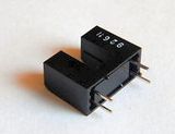
(Slotted Optical Switch
(Slotted Optical Switch Diagram)


Atmel Microprocessor Source Code:
//Program Written By: Brad Raedel
//03242020 - Revision A
//** All 8 Profiles active
//** Outputs now change to inputs when not active - This allows the pull-up resistors to control the high logic
//03162020 - Revision 1 - Just get it working

//Up
int Opto1 = 2;    //Input Pin 2
int Opto2 = 3;    //Input Pin 3
int Opto3 = 4;    //Input Pin 4
int Up = 9;      //Output to Game - Pin 10
int Dn = 10;      //Output to Game - Pin 11
//Down
int Opto4 = 5;    //Input Pin 5
int Opto5 = 6;    //Input Pin 6
int Opto6 = 7;    //Input Pin 7
int Left = 11;    //Output to Game - Pin 12
int Right = 12;   //Output to Game - Pin 13

//Option Switches - These will be used to select mode/options (0 to 15)
int Op1 = A0; //1
int Op2 = A1; //2
int Op3 = A2; //4
int Op4 = A3; //8
int OpVal = 0; //Default to zero

bool Opto1St;   //Opto States
bool Opto2St;
bool Opto3St;
bool Opto4St;
bool Opto5St;
bool Opto6St;
bool UpSt;      //Set HIGH when stick is UP
bool DnSt;      //Set HIGH when Stick is DOWN
bool LtSt;      //Set HIGH when stick is LEFT
bool RtSt;      //Set HIGH when Stick is RIGHT
bool LockedStUD;//Used to Latch the UP or DOWN position
bool LockedStLR;//Used to Latch the LEFT or RIGH postion
int UpVal = 3;    //Store the Up position (0-2)
int DnVal = 3;    //Store the Down postion (0-2)
int UpDnPos = 3;  //Absolute postion of Up/Down 0 = Top, 6 = Bottom, 3 is Center/Neutral
int LtVal = 3;    //Store the Left position (0-2)
int RtVal = 3;    //Store the Right position (0-2)
int LtRtPos = 3;  //Absolute postion of Left/Right 0 = Left, 6 = Right, 3 is Center/Neutral
int AbsPos = 24;
int i = 0;

//Rows Then Columns - Stored Like this { {Row 0 - 0 to 48},{Row 2 - 0 to 48}...etc..
// 8-Way Standard
const bool  Up8WayStd[49]  =  {1,1,1,1,1,1,1,1,1,1,1,1,1,1,0,0,1,0,1,0,0,0,0,0,0,0,0,0,0,0,0,0,0,0,0,0,0,0,0,0,0,0,0,0,0,0,0,0,0} ;
const bool  Dn8WayStd[49]  =  {0,0,0,0,0,0,0,0,0,0,0,0,0,0,0,0,0,0,0,0,0,0,0,0,0,0,0,0,0,0,1,0,1,0,0,1,1,1,1,1,1,1,1,1,1,1,1,1,1} ;
const bool  Lt8WayStd[49]  =  {1,1,0,0,0,0,0,1,1,0,0,0,0,0,1,1,1,0,0,0,0,1,1,0,0,0,0,0,1,1,1,0,0,0,0,1,1,0,0,0,0,0,1,1,0,0,0,0,0} ;
const bool  Rt8WayStd[49]  =  {0,0,0,0,0,1,1,0,0,0,0,0,1,1,0,0,0,0,1,1,1,0,0,0,0,0,1,1,0,0,0,0,1,1,1,0,0,0,0,0,1,1,0,0,0,0,0,1,1} ;
// 8-Way with NO Dead Zone
const bool  Up8WayNoDZ[49]  = {1,1,1,1,1,1,1,1,1,1,1,1,1,1,0,0,1,1,1,0,0,0,0,0,0,0,0,0,0,0,0,0,0,0,0,0,0,0,0,0,0,0,0,0,0,0,0,0,0} ;
const bool  Dn8WayNoDZ[49]  = {0,0,0,0,0,0,0,0,0,0,0,0,0,0,0,0,0,0,0,0,0,0,0,0,0,0,0,0,0,0,1,1,1,0,0,1,1,1,1,1,1,1,1,1,1,1,1,1,1} ;
const bool  Lt8WayNoDZ[49]  = {1,1,0,0,0,0,0,1,1,0,0,0,0,0,1,1,1,0,0,0,0,1,1,1,0,0,0,0,1,1,1,0,0,0,0,1,1,0,0,0,0,0,1,1,0,0,0,0,0} ;
const bool  Rt8WayNoDZ[49]  = {0,0,0,0,0,1,1,0,0,0,0,0,1,1,0,0,0,0,1,1,1,0,0,0,0,1,1,1,0,0,0,0,1,1,1,0,0,0,0,0,1,1,0,0,0,0,0,1,1} ;
// 8-Way with Dead Zone
const bool  Up8WayDZ[49]  = {1,1,1,1,1,1,1,1,1,1,1,1,1,1,0,0,0,0,0,0,0,0,0,0,0,0,0,0,0,0,0,0,0,0,0,0,0,0,0,0,0,0,0,0,0,0,0,0,0} ;
const bool  Dn8WayDZ[49]  = {0,0,0,0,0,0,0,0,0,0,0,0,0,0,0,0,0,0,0,0,0,0,0,0,0,0,0,0,0,0,0,0,0,0,0,1,1,1,1,1,1,1,1,1,1,1,1,1,1} ;
const bool  Lt8WayDZ[49]  = {1,1,0,0,0,0,0,1,1,0,0,0,0,0,1,1,0,0,0,0,0,1,1,0,0,0,0,0,1,1,0,0,0,0,0,1,1,0,0,0,0,0,1,1,0,0,0,0,0} ;
const bool  Rt8WayDZ[49]  = {0,0,0,0,0,1,1,0,0,0,0,0,1,1,0,0,0,0,0,1,1,0,0,0,0,0,1,1,0,0,0,0,0,1,1,0,0,0,0,0,1,1,0,0,0,0,0,1,1} ;
//4-Way Standard
const bool  Up4WayStd[49]  =  {0,1,1,1,1,1,0,0,0,1,1,1,0,0,0,0,0,1,0,0,0,0,0,0,0,0,0,0,0,0,0,0,0,0,0,0,0,0,0,0,0,0,0,0,0,0,0,0,0} ;
const bool  Dn4WayStd[49]  =  {0,0,0,0,0,0,0,0,0,0,0,0,0,0,0,0,0,0,0,0,0,0,0,0,0,0,0,0,0,0,0,1,0,0,0,0,0,1,1,1,0,0,0,0,1,1,1,1,0} ;
const bool  Lt4WayStd[49]  =  {0,0,0,0,0,0,0,1,0,0,0,0,0,0,1,1,0,0,0,0,0,1,1,1,0,0,0,0,1,1,0,0,0,0,0,1,0,0,0,0,0,0,0,0,0,0,0,0,0} ;
const bool  Rt4WayStd[49]  =  {0,0,0,0,0,0,0,0,0,0,0,0,0,1,0,0,0,0,0,1,1,0,0,0,0,1,1,1,0,0,0,0,0,1,1,0,0,0,0,0,0,1,0,0,0,0,0,0,0} ;
//4-Way Corners L/R
const bool  Up4WayLR[49]  = {0,1,1,1,1,1,0,0,1,1,1,1,1,0,0,0,0,1,0,0,0,0,0,0,0,0,0,0,0,0,0,0,0,0,0,0,0,0,0,0,0,0,0,0,0,0,0,0,0} ;
const bool  Dn4WayLR[49]  = {0,0,0,0,0,0,0,0,0,0,0,0,0,0,0,0,0,0,0,0,0,0,0,0,0,0,0,0,0,0,0,1,0,0,0,0,1,1,1,1,1,0,0,1,1,1,1,1,0} ;
const bool  Lt4WayLR[49]  = {1,0,0,0,0,0,0,1,0,0,0,0,0,0,1,1,1,0,0,0,0,1,1,1,0,0,0,0,1,1,1,0,0,0,0,1,0,0,0,0,0,0,1,0,0,0,0,0,0} ;
const bool  Rt4WayLR[49]  = {0,0,0,0,0,0,1,0,0,0,0,0,0,1,0,0,0,0,1,1,1,0,0,0,0,1,1,1,0,0,0,0,1,1,1,0,0,0,0,0,0,1,0,0,0,0,0,0,1} ;
//4-Way Corners U/D
const bool  Up4WayUD[49]  = {1,1,1,1,1,1,1,0,1,1,1,1,1,0,0,0,1,1,1,0,0,0,0,0,0,0,0,0,0,0,0,0,0,0,0,0,0,0,0,0,0,0,0,0,0,0,0,0,0} ;
const bool  Dn4WayUD[49]  = {0,0,0,0,0,0,0,0,0,0,0,0,0,0,0,0,0,0,0,0,0,0,0,0,0,0,0,0,0,0,1,1,1,0,0,0,1,1,1,1,1,0,1,1,1,1,1,1,1} ;
const bool  Lt4WayUD[49]  = {0,0,0,0,0,0,0,1,0,0,0,0,0,0,1,1,0,0,0,0,0,1,1,1,0,0,0,0,1,1,0,0,0,0,0,1,0,0,0,0,0,0,0,0,0,0,0,0,0} ;
const bool  Rt4WayUD[49]  = {0,0,0,0,0,0,0,0,0,0,0,0,0,1,0,0,0,0,0,1,1,0,0,0,0,1,1,1,0,0,0,0,0,1,1,0,0,0,0,0,0,1,0,0,0,0,0,0,0} ;
// 2-Way Horizontal
const bool  Up2WayH[49]  =  {0,0,0,0,0,0,0,0,0,0,0,0,0,0,0,0,0,0,0,0,0,0,0,0,0,0,0,0,0,0,0,0,0,0,0,0,0,0,0,0,0,0,0,0,0,0,0,0,0} ;
const bool  Dn2WayH[49]  =  {0,0,0,0,0,0,0,0,0,0,0,0,0,0,0,0,0,0,0,0,0,0,0,0,0,0,0,0,0,0,0,0,0,0,0,0,0,0,0,0,0,0,0,0,0,0,0,0,0} ;
const bool  Lt2WayH[49]  =  {1,1,1,0,0,0,0,1,1,1,0,0,0,0,1,1,1,0,0,0,0,1,1,1,0,0,0,0,1,1,1,0,0,0,0,1,1,1,0,0,0,0,1,1,1,0,0,0,0} ;
const bool  Rt2WayH[49]  =  {0,0,0,0,1,1,1,0,0,0,0,1,1,1,0,0,0,0,1,1,1,0,0,0,0,1,1,1,0,0,0,0,1,1,1,0,0,0,0,1,1,1,0,0,0,0,1,1,1} ;
// 2-Way Vertical
const bool  Up2WayV[49]  =  {1,1,1,1,1,1,1,1,1,1,1,1,1,1,1,1,1,1,1,1,1,0,0,0,0,0,0,0,0,0,0,0,0,0,0,0,0,0,0,0,0,0,0,0,0,0,0,0,0} ;
const bool  Dn2WayV[49]  =  {0,0,0,0,0,0,0,0,0,0,0,0,0,0,0,0,0,0,0,0,0,0,0,0,0,0,0,0,1,1,1,1,1,1,1,1,1,1,1,1,1,1,1,1,1,1,1,1,1} ;
const bool  Lt2WayV[49]  =  {0,0,0,0,0,0,0,0,0,0,0,0,0,0,0,0,0,0,0,0,0,0,0,0,0,0,0,0,0,0,0,0,0,0,0,0,0,0,0,0,0,0,0,0,0,0,0,0,0} ;
const bool  Rt2WayV[49]  =  {0,0,0,0,0,0,0,0,0,0,0,0,0,0,0,0,0,0,0,0,0,0,0,0,0,0,0,0,0,0,0,0,0,0,0,0,0,0,0,0,0,0,0,0,0,0,0,0,0} ;

bool  UpOut[49] = {};
bool  DnOut[49] = {};
bool  LtOut[49] = {};
bool  RtOut[49] = {};
void setup() {
//Serial.begin(57600);    //Disable when not debugging
pinMode(Opto1,INPUT);   //Set Direction of physical inputs/outputs
pinMode(Opto2,INPUT);
pinMode(Opto3,INPUT);
pinMode(Opto4,INPUT);
pinMode(Opto5,INPUT);
pinMode(Opto6,INPUT);
pinMode(Up,INPUT);
pinMode(Dn,INPUT);
pinMode(Left,INPUT);
pinMode(Right,INPUT);
pinMode(Op1,INPUT);
pinMode(Op2,INPUT);
pinMode(Op3,INPUT);
pinMode(Op4,INPUT);

//Let's get our DIP Switch settings (Will = 0 to 15)
if (digitalRead(Op1) == HIGH)
{
  OpVal = 1;
}
if (digitalRead(Op2) == HIGH)
{
  OpVal = OpVal + 2;
}
if (digitalRead(Op3) == HIGH)
{
  OpVal = OpVal + 4;
}
if (digitalRead(Op4) == HIGH)
{
  OpVal = OpVal + 8;
}
//Serial.println(OpVal);
  switch (OpVal) {
  case 0:         //DIP Switch 0 - 8-Way - No Dead zone - This routine copies the array - Only on setup, not during loop/runtime
  // 8WayStd
    i = 0;
    while( i < 49 ){
    UpOut[ i ] = Up8WayStd[ i ];
    DnOut[ i ] = Dn8WayStd[ i ];
    LtOut[ i ] = Lt8WayStd[ i ];
    RtOut[ i ] = Rt8WayStd[ i ];
    ++i;}
  break;
  case 1:     //DIP Switch 1 -
  // 8WayNoDZ
    i = 0;
    while( i < 49 ){
    UpOut[ i ] = Up8WayNoDZ[ i ];
    DnOut[ i ] = Dn8WayNoDZ[ i ];
    LtOut[ i ] = Lt8WayNoDZ[ i ];
    RtOut[ i ] = Rt8WayNoDZ[ i ];
    ++i;}
  break;
 case 2:     //DIP Switch 2 -
  // 8WayDZ
    i = 0;
    while( i < 49 ){
    UpOut[ i ] = Up8WayDZ[ i ];
    DnOut[ i ] = Dn8WayDZ[ i ];
    LtOut[ i ] = Lt8WayDZ[ i ];
    RtOut[ i ] = Rt8WayDZ[ i ];
    ++i;}
  break;
  case 3:     //DIP Switch 3 -
  // 4WayStd
    i = 0;
    while( i < 49 ){
    UpOut[ i ] = Up4WayStd[ i ];
    DnOut[ i ] = Dn4WayStd[ i ];
    LtOut[ i ] = Lt4WayStd[ i ];
    RtOut[ i ] = Rt4WayStd[ i ];
    ++i;}
  break;
  case 4:     //DIP Switch 4 -
  // 4WayLR
    i = 0;
    while( i < 49 ){
    UpOut[ i ] = Up4WayLR[ i ];
    DnOut[ i ] = Dn4WayLR[ i ];
    LtOut[ i ] = Lt4WayLR[ i ];
    RtOut[ i ] = Rt4WayLR[ i ];
    ++i;}
  break;
    case 5:     //DIP Switch 5 -
  // 4WayUD
    i = 0;
    while( i < 49 ){
    UpOut[ i ] = Up4WayUD[ i ];
    DnOut[ i ] = Dn4WayUD[ i ];
    LtOut[ i ] = Lt4WayUD[ i ];
    RtOut[ i ] = Rt4WayUD[ i ];
    ++i;}
  break;
    case 6:     //DIP Switch 6 -
  // 2WayH
    i = 0;
    while( i < 49 ){
    UpOut[ i ] = Up2WayH[ i ];
    DnOut[ i ] = Dn2WayH[ i ];
    LtOut[ i ] = Lt2WayH[ i ];
    RtOut[ i ] = Rt2WayH[ i ];
    ++i;}
  break;
      case 7:     //DIP Switch 7 -
  // 2WayV
    i = 0;
    while( i < 49 ){
    UpOut[ i ] = Up2WayV[ i ];
    DnOut[ i ] = Dn2WayV[ i ];
    LtOut[ i ] = Lt2WayV[ i ];
    RtOut[ i ] = Rt2WayV[ i ];
    ++i;}
  break;

  }
}

//Main Program that loops
void loop() {
// Up/Down Logic
Opto1St = digitalRead(Opto1); //Read Optical Switch 1
Opto2St = digitalRead(Opto2); //Read Optical Switch 2
Opto3St = digitalRead(Opto3); //Read Optical Switch 2
if (Opto1St == true && Opto2St == true && Opto3St == true)  //Determine if the joystick is in the center
{
  LockedStUD = false;   //Unlatch to allow Up or Down to assume control
  UpSt = false;         //Clear Up State
  DnSt = false;         //Clear Down State
  UpDnPos = 3;          //Set Vertical position to center
}
//Latch Direction (Determines if up or down
 if (Opto1St == false && LockedStUD == false)   //UP if True
      {
        UpSt = true;          //Set UP State to TRUE
        LockedStUD = true;    //We lock the State so DOWN can't Steal it!
      }
if (Opto3St == false && LockedStUD == false)    //DOWN if True
      {
        DnSt = true;        //Set DOWN State to TRUE
        LockedStUD = true;  //We lock the State so UP can't Steal it!
      }
//We will figure out what row we are in (0 to 6 - 3 is center)
if (UpSt == true) //Up doesn't need any change since adding the Optical Switches is 0 to 2
{
  UpVal = Opto1St + Opto2St + Opto3St;
  UpDnPos = UpVal;
}
if (DnSt == true)     //For Down, we determine how many Optical Switches are Low, add them up then use a look-up table to generate the position 4 to 6
{
  DnVal = Opto1St + Opto2St + Opto3St;
  switch (DnVal) {
  case 0:      //All Optos are LOW
      UpDnPos = 6;
  break;
  case 1:     //Two of the Optos are LOW
      UpDnPos = 5;
  break;
  case 2:    //One of the Optos are LOW (The others are still High)
      UpDnPos = 4;
  break;
  }
}

// Left/Right Logic
Opto4St = digitalRead(Opto4); //Read Optical Switch 4
Opto5St = digitalRead(Opto5); //Read Optical Switch 5
Opto6St = digitalRead(Opto6); //Read Optical Switch 6
if (Opto4St == true && Opto5St == true && Opto6St == true)  //Determine if the joystick is in the center
{
  LockedStLR = false;   //Unlatch to allow Left or Right to assume control
  LtSt = false;         //Clear Left State
  RtSt = false;         //Clear Right State
  LtRtPos = 3;          //Set Horizontal position to center
}
//Latch Direction (Determines if Left or Right
 if (Opto4St == false && LockedStLR == false)   //Right if True
      {
        RtSt = true;          //Set Right State to TRUE
        LockedStLR = true;    //We lock the State so Left can't Steal it!
      }
if (Opto6St == false && LockedStLR == false)    //Left if True
      {
        LtSt = true;        //Set Left State to TRUE
        LockedStLR = true;  //We lock the State so Right can't Steal it!
      }
//We will figure out what row we are in (0 to 6 - 3 is center)
if (LtSt == true) //Up doesn't need any change since adding the Optical Switches is 0 to 2
{
  LtVal = Opto4St + Opto5St + Opto6St;
  LtRtPos = LtVal;
}
if (RtSt == true)     //For Down, we determine how many Optical Switches are Low, add them up then use a look-up table to generate the position 4 to 6
{
  RtVal = Opto4St + Opto5St + Opto6St;
  switch (RtVal) {
  case 0:      //All Optos are LOW
      LtRtPos = 6;
  break;
  case 1:     //Two of the Optos are LOW
      LtRtPos = 5;
  break;
  case 2:    //One of the Optos are LOW (The others are still High)
      LtRtPos = 4;
  break;
  }
}
//Calculate the absolute position
AbsPos = (UpDnPos * 7) + LtRtPos;
   //Serial.println(AbsPos);
  //Output
  //UP
   if (UpOut[AbsPos] == true){
    pinMode(Up,OUTPUT);
    digitalWrite(Up,LOW);
   }
   else {
    pinMode(Up,INPUT);
   }
    //Down
   if (DnOut[AbsPos] == true){
    pinMode(Dn,OUTPUT);
    digitalWrite(Dn,LOW);
   }
   else {
    pinMode(Dn,INPUT);
   }
   //Left
   if (LtOut[AbsPos] == true){
    pinMode(Left,OUTPUT);
    digitalWrite(Left,LOW);
   }
   else {
    pinMode(Left,INPUT);
   }
   //Right
   if (RtOut[AbsPos] == true){
    pinMode(Right,OUTPUT);
    digitalWrite(Right,LOW);
   }
   else {
    pinMode(Right,INPUT);
   }
}