Difference between revisions of "Defender"
Jump to navigation
Jump to search
| Line 86: | Line 86: | ||
*** Is used to allow the program to enable or disable the Multiplexers (Muxers) | *** Is used to allow the program to enable or disable the Multiplexers (Muxers) | ||
*** W2 should always be connected there is no reason to remove jumper | *** W2 should always be connected there is no reason to remove jumper | ||
| + | |||
*; Connections | *; Connections | ||
** Upright | ** Upright | ||
Revision as of 05:13, 4 February 2020
Released - 1981
Contents
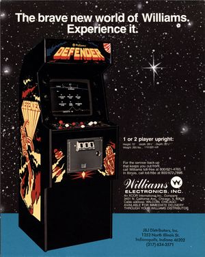
Upright Cabinet
- Overall Dimensions/Weight

| Height | Width | Depth | Weight |
|---|---|---|---|
| 72" | 26" | 32.5" (32 1/2") | 265 lbs. |
- Marquee Information
| Height | Width |
|---|---|
| 7.75" (7 3/4") | 24.375" (24 3/8") |

- Control Panel Information
Joystick: 2-way - Leaf Switch (up, down) Buttons: 5 Fire-Thrust-Reverse-Hyperspace-Smart Bomb
Cocktail Cabinet
- Overall Dimensions/Weight
Documentation
Drawings/Schematics
Early Drawings
Later Drawings
- Front Cover
- Table Of Contents
- Board Layout Diagram 1
- Board Layout Diagram 2
- MPU Layout Diagram 1 (R8570)
- MPU Layout Diagram 2 (Parts List) (R8570)
- MPU Schematic/Logic 1 (R8570)
- MPU Schematic/Logic 2 (R8570)
- Interface/Widget Board (C8573)
- ROM Board Layout Diagram (D8572)
- ROM Board Schematic (D8572)
- Power Supply Diagram (D8359)
- Power Supply Schematic (D8359)
- Cabinet Power Schematic
- Power Board Diagram (D8373)
- Early Sound Board Diagram/Layout (D8121)
- Early Sound Board Schematic (D8121)
- Later Sound Board Diagram/Layout (D8224)
- Later Sound Board Schematic (D8224)
- Manual Stored Here
- Parts Catalog Stored Here
Boards
ROM Board
Interface Board (I/O, Widget)
Click here for more information..
Description: The interface board is used to provide input ports that allow the physical connection of user inputs from the Control Panel. This board uses a 6821 PIA (peripheral interface adapter) that digitizes all inputs and provides the switch state to the MPU board when requested.
- Jumpers
- W1
- Is used to identify to the system if the game is an Upright or Cocktail
- W1 Removed - Cocktail Game - Screen Flip and unique controls (+5v Pull-Up resistor to PIA)
- W1 Installed - Upright Game - 2 Players share same controls, no screen flip (Connects PIA input to Ground)
- Notes: Green Rom Version has no support for Cocktail Mode
- W2
- Is used to allow the program to enable or disable the Multiplexers (Muxers)
- W2 should always be connected there is no reason to remove jumper
- Connections
- Upright
- 3J2 Connector (Upper - Furthest from ribbon cable - Pin 1 is lowest - 10 Pin Molex PCB Headers - .156")
- 'Fire' Button - (ORG-BRN) - PIA Pin 2
- 'Thrust' Button - (ORG-RED) - PIA Pin 3
- 'Smart Bomb' Button - (ORG) - PIA Pin 4
- 'Hyperspace' Button - (ORG-YEL) - PIA Pin 5
- '2-Player Start' Button - (ORG-GRN) - PIA Pin 6
- '1-Player Start' Button - (ORG-BLU) - PIA Pin 7
- 'Reverse' Button - (ORG-VIO) - PIA Pin 8
- 'Down' Joystick - (ORG-GRY) - PIA Pin 9
- Key (Pin Removed)
- NC (No Connection)
- 3J3 Connector (Lower closest to ribbon cable - Pin 1 is lowest - 10 Pin Molex PCB Headers - .156")
- Up' Joystick - (ORG-WHT) - PIA Pin 10
- NC (No Connection)
- NC
- NC
- NC
- Key - Pin Removed
- NC
- NC
- NC
- Ground - (ORG-BLK) - Common to all switches and joystick
- 3J2 Connector (Upper - Furthest from ribbon cable - Pin 1 is lowest - 10 Pin Molex PCB Headers - .156")
- Cocktail
- 3J2 Connector (Upper - Furthest from ribbon cable - Pin 1 is lowest - 10 Pin Molex PCB Headers - .156")
- 'Fire' Button (P1) - (ORG-BRN) - PIA Pin 2
- 'Thrust' Button (P1) - (ORG-RED) - PIA Pin 3
- 'Smart Bomb' Button (P1) - (ORG) - PIA Pin 4
- 'Hyperspace' Button (P1) - (ORG-YEL) - PIA Pin 5
- '2-Player Start' Button (P1) - (ORG-GRN) - PIA Pin 6
- '1-Player Start' Button (P1) - (ORG-BLU) - PIA Pin 7
- 'Reverse' Button (P1) - (ORG-VIO) - PIA Pin 8
- 'UP' Joystick (P1) - (ORG-GRY) - PIA Pin 9
- Key (Pin Removed)
- Ground - (RED-BLK) - Common to all P2 Controls)
- 3J3 Connector (Lower closest to ribbon cable - Pin 1 is lowest - 10 Pin Molex PCB Headers - .156")
- Down' Joystick (P1)- (ORG-WHT) - PIA Pin 10
- 'Up' Joystick (P2) - (RED-BRN)
- 'Thrust' Button (P2) - (RED)
- 'Smart Bomb' Button (P2) - (RED-ORG)
- 'Hyperspace' Button (P2) - (RED-YEL)
- Key - Pin Removed
- 'Reverse' Button (P2) - (RED-VIO)
- 'Fire' Button (P2) - (RED-GRY)
- 'Down' Joystick (P2) - (RED-WHT)
- Ground - (ORG-BLK) - (Common to all P1 Controls)
- Ribbon Cable - Pinout
- D4 - PIA Pin 29
- NMI(NOT) - PIA No Connection
- D7 - PIA Pin 26
- FIRQ(NOT) - PIA No Connection
- D6 - PIA Pin 27
- RW (Read/Write) - PIA Pin 21
- D5 - PIA Pin 28
- Reset(NOT) - PIA Pin 34
- D2 - PIA Pin 31
- +5vdc (Power for board) - PIA Pin 20
- D1 - PIA Pin 32
- D0 - PIA Pin 33
- D3 - PIA Pin 30
- E(Enable) - PIA Pin 25
- PIA(NOT) - PIA Pin 23 via IC4(14049 Hex Inverter Pin 11 to 12)
- Ground - PIA Pin 6
- A0 - PIA Pin 36
- A1 - PIA Pin 35
- A2 - PIA Pin 24
- A3 - PIA Pin 22 via IC4(14049 Hex Inverter - Pin 9 to 10)
- ;Jumpers
- ;W1
- Is used to identify to the system if the game is an Upright or Cocktail
- W1 Removed - Cocktail Game - Screen Flip and unique controls (+5v Pull-Up resistor to PIA)
- W1 Installed - Upright Game - 2 Players share same controls, no screen flip (Connects PIA input to Ground)
- Notes: Green Rom Version has no support for Cocktail Mode
- ;W2
- Is used to allow the program to enable or disable the Multiplexers (Muxers)
- W2 should always be connected there is no reason to remove jumper
- ;W1
- ;Connections